In industrial plants, shell and tube heat exchangers are vital for heating or cooling process fluids. Keeping them running safely and reliably depends on a critical component: the girth flange.
This guide explains what a girth flange is, how it works, and why its design is so important for a leak-free and efficient heat exchanger.
What is a Girth Flange in a Heat Exchanger?
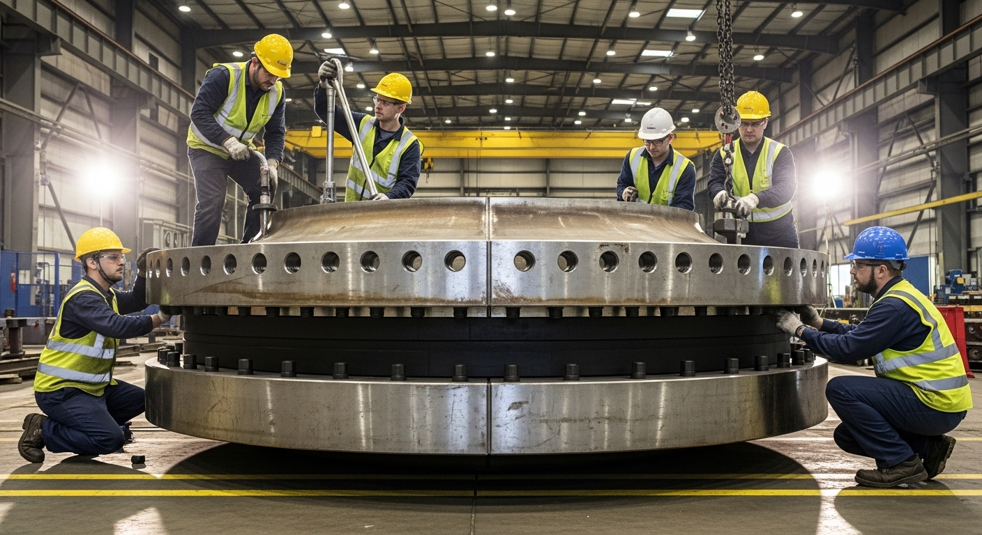
A girth flange, also called a body flange, is a large, circular connector that joins the main sections of a heat exchanger. Think of it as the strong "clasp" that holds the exchanger together.
Unlike a standard pipe flange that connects to external piping, a girth flange is part of the exchanger's main structure. For example, it connects the shell to the channel (front head) or the shell to the rear head. Its main jobs are:
- Pressure Containment: It seals the joint to safely contain the internal fluid pressure and temperature.
- Access for Maintenance: It allows the heat exchanger to be opened for cleaning, inspecting tubes, or performing repairs.
- Structural Integrity: It provides a rigid, aligned connection that resists forces from pressure and connected piping.
Materials and Types: Choosing the Right Girth Flange
Selecting the correct material and flange type is based on the specific fluid, pressure, and temperature inside the exchanger.
Common Materials
The flange material must withstand corrosion and pressure. Common choices include:
- Carbon Steel (e.g., SA-105): A cost-effective choice for many general services.
- Stainless Steel (e.g., SA-182 F304/316): For corrosion resistance in chemical or marine environments.
- Low-Alloy Steel (e.g., SA-182 F11, F22): Designed for high-temperature service in power or refinery applications.
- Duplex Stainless Steel (e.g., SA-182 F51, F53): Offers high strength and excellent resistance to cracking.
- Nickel Alloys (e.g., Alloy 625): Used for the most aggressive corrosive environments.
Flange Types
There are two main types, each suited for different needs:
| Type | Description | Best For |
|---|---|---|
| Welded Hub Joint | Has a central hub welded to the inside diameter (ID) of the shell or channel. Creates a strong, permanent connection with a smooth internal bore for good fluid flow. | High-pressure applications, severe thermal cycling, and where a rigid, reliable connection is critical. |
| Loose Ring Type (Slip-On) | Slips over the shell or channel and is welded to the outside diameter (OD). Offers more flexibility and is easier to align during fabrication. | Lower pressure applications, cost-sensitive projects, or where future modifications are considered. |
Critical Design Challenges and Leak Prevention
The primary goal of girth flange design is to prevent leaks, which can cause safety hazards, environmental issues, and costly downtime. A major challenge is thermal distortion.
When different parts of the heat exchanger heat up or cool down at different rates, the metal can warp. This is especially a problem in multi-pass exchangers where one side of the tubesheet can be much hotter than the other. The industry standard API 660 requires special analysis if this temperature difference exceeds 110°C (200°F).
To prevent leaks from thermal distortion and other stresses, engineers use several design strategies:
- Increase Flange Rigidity: Design a stiffer flange that resists bending.
- Enhance Bolt Capacity: Use more or larger bolts to ensure the joint stays tight.
- Add Extra Thickness: Include a buffer of extra material (5–10 mm) in the flange and tubesheet.
These designs follow strict pressure vessel codes, primarily ASME Section VIII, Division 1, often supplemented by the TEMA (Tubular Exchanger Manufacturers Association) standards for heat exchangers.
Gaskets and Proper Assembly: Sealing the Deal
Even a perfectly designed flange can leak if the seal isn't right. The gasket and how the joint is assembled are critical.
- Gasket Selection: Common choices for girth flanges include spiral-wound or metal-jacketed gaskets, selected based on the specific pressure, temperature, and fluid.
- Proper Bolting: Tightening the bolts correctly is a science, not just a manual task. Modern practice follows guidelines like ASME PCC-1, which calculates the precise bolt stress needed to compress the gasket enough for a leak-proof seal during operation.
Frequently Asked Questions
Q: What's the difference between a girth flange and a standard pipe flange?
A girth flange is a custom part of the heat exchanger's main body. A standard pipe flange (like an ANSI B16.5 flange) is an off-the-shelf part used to connect pipes to nozzles on the outside of the exchanger.
Q: Can we use a standard ANSI flange instead of a custom girth flange?
Sometimes on small, low-pressure exchangers for cost savings. However, this often comes with restrictions, and the pressure rating may need to be re-calculated.
Q: What are the most common causes of girth flange leakage?
The main causes are thermal distortion, improper assembly (uneven bolt tightening), incorrect gasket selection, and vibrations.
Q: What does replacing a girth flange involve?
It is a major task for repair or modification. It requires strict safety steps, specialized cutting, and ensuring the new flange is perfectly aligned and welded to specification.
Q: What does "TEMA" stand for, and why is it important?
TEMA stands for the Tubular Exchanger Manufacturers Association. Its standards provide essential design rules, tolerances, and a classification system (like TEMA "AES") that defines construction types for shell and tube heat exchangers.